Project snapshot
- Problem
- Design an autonomous miniature waste-collection robot that could navigate roadway tiles, detect bins, avoid obstacles, collect and deposit contents, and return bins under strict size, time, budget, and autonomy constraints.
- My role
- Team project contribution focused on drive sizing and selection, main mechanical CAD integration, mecanum-drive packaging, storage/deposit mechanism design, sensor mounting, fabrication drawings, and mechanical iteration.
- Tools
- Autodesk Inventor, CAD assemblies, STL/DWG drawing output, 3D-printable part design, mechanical calculations, mecanum-drive sizing, subsystem testing, and team engineering documentation.
- Design constraints
- Shoebox-size submission limit, material budget cap, Li-poly energy limit, limited remote commands, no internet dependency, obstacle/bin sensing, and bin-return accuracy requirements.
- Outcome
- Team finished second in the cohort. My documented work covered CAD-backed robot subsystems, manufacturing drawings, drive sizing, storage-capacity analysis, mounting hardware, and mechanical iteration.
- Relevance
- Autonomous robotics, navigation behaviour, mechanical prototyping, sensor integration, practical CAD packaging, control logic, testing, and multidisciplinary team engineering.
Visual proof
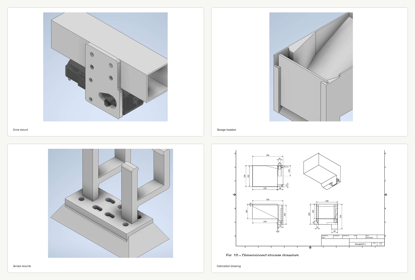
Interactive course behaviour model
This static browser model uses the original modular tile images from the METR4810 rules PDF. It randomises a valid tile course with branches and possible closed loops, places red and yellow bins on roadside positions, then animates a simple collection strategy: map the course while collecting yellow-lid bins, deposit at the yellow zone, then use remembered red-bin locations for a shorter second pass.
My contribution
- Worked on the drive subsystem analysis and selected a four-wheel mecanum-drive layout for omnidirectional alignment and zero-radius turning.
- Estimated robot mass, wheel torque, acceleration requirements, and motor suitability for the expected robot load and drivetrain geometry.
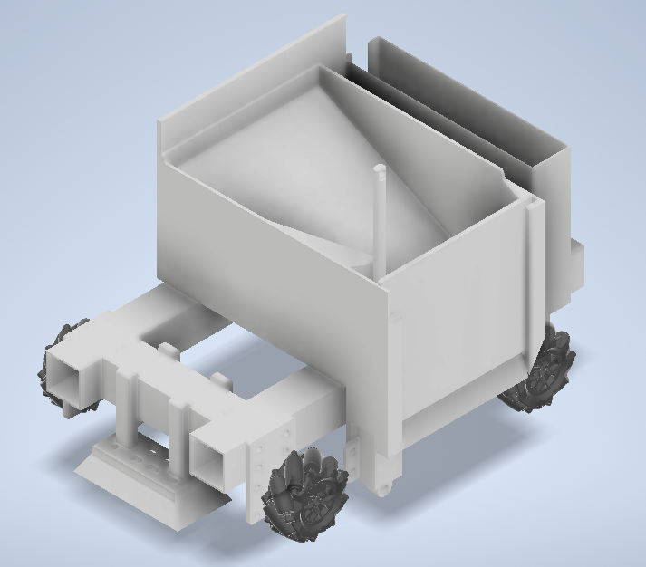
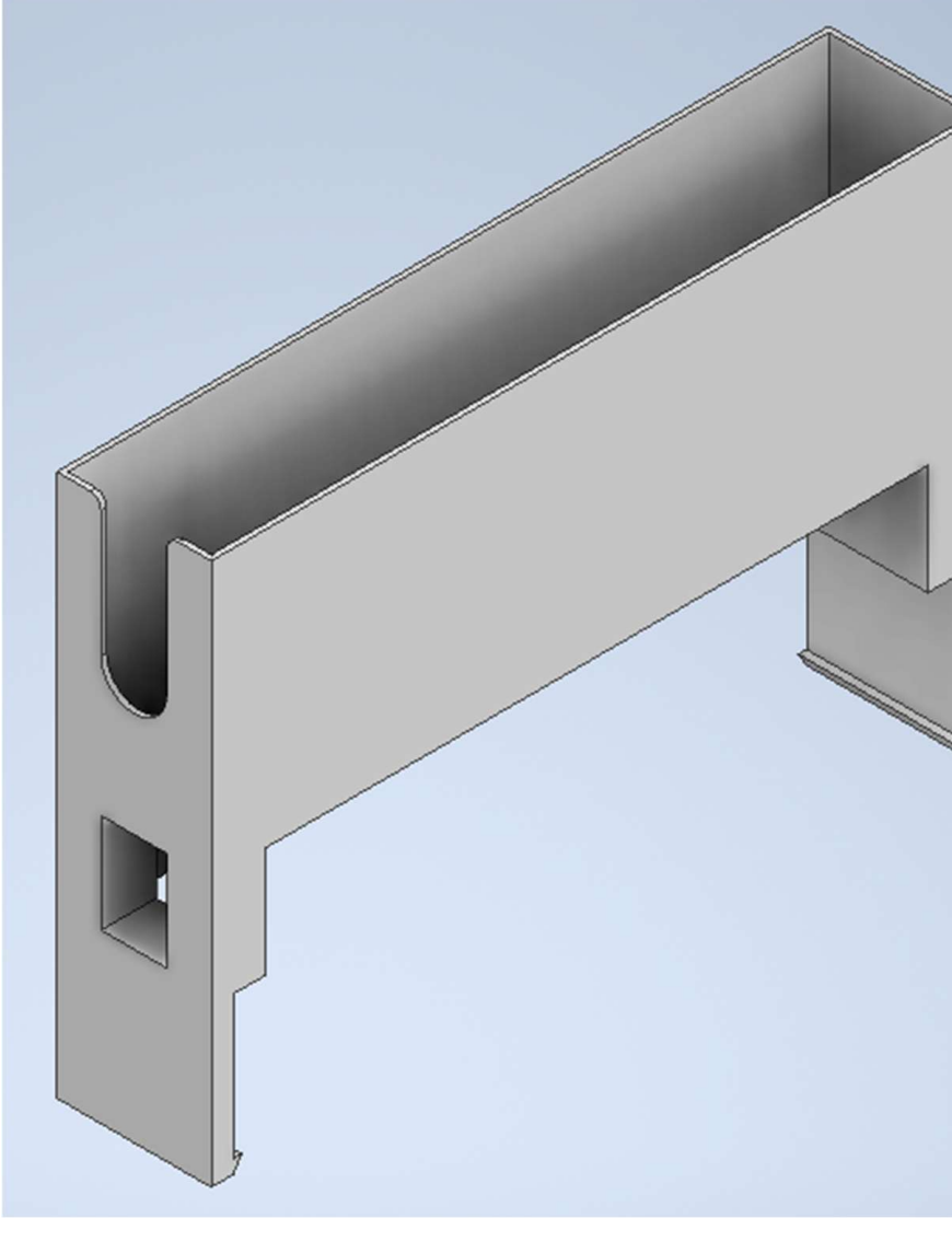
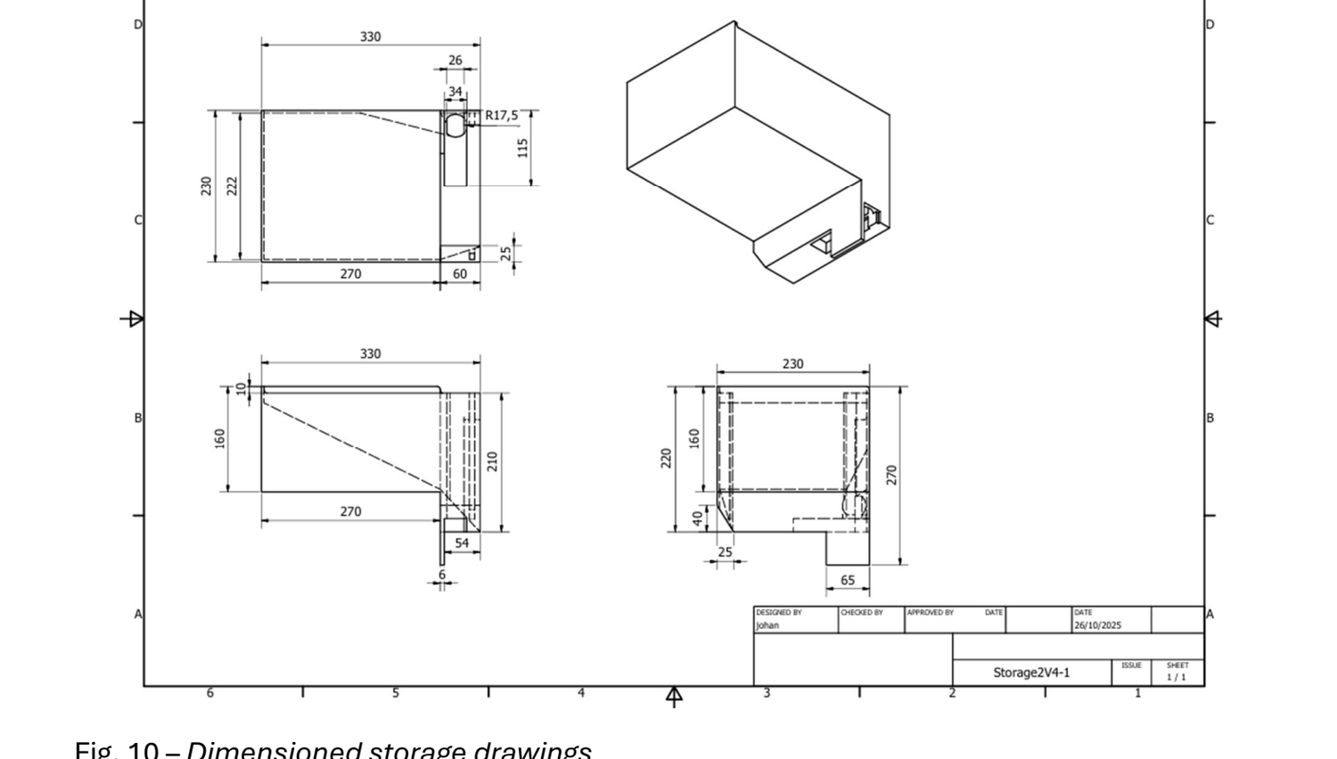
- Designed and iterated the onboard storage and deposit mechanism using a tapered bin, side guides, sliding trapdoor, and linear-actuator concept.
- Created and integrated CAD for the main mechanical package, including motor mounts, storage container, deposit mechanism, and sensor mounting hardware.
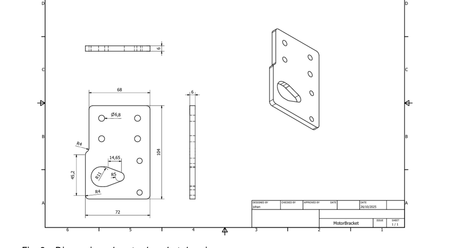
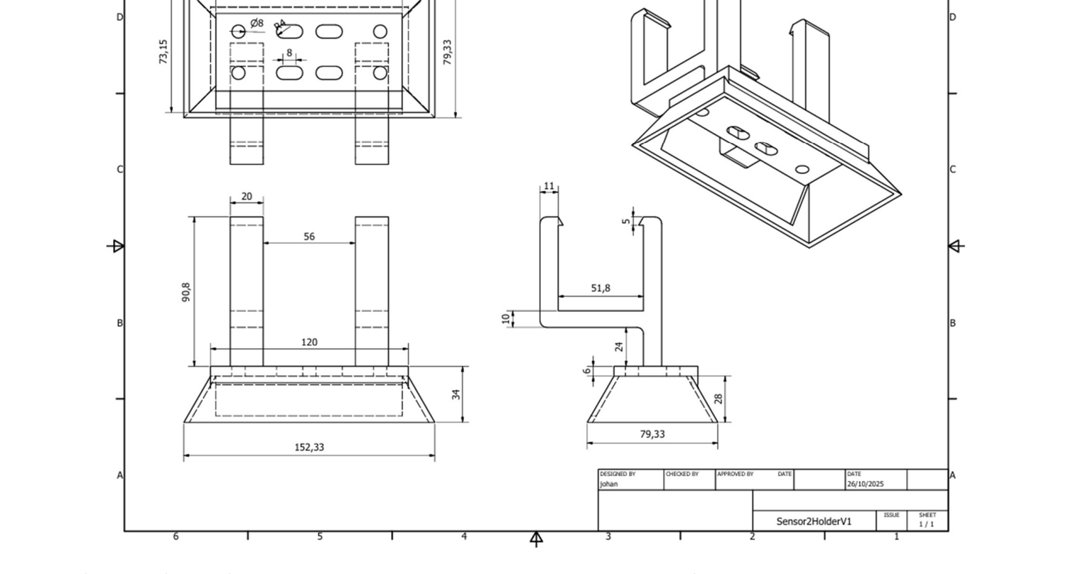
- Produced drawing and STL-style manufacturing documentation for parts that needed to be fabricated, printed, assembled, or checked by the team.
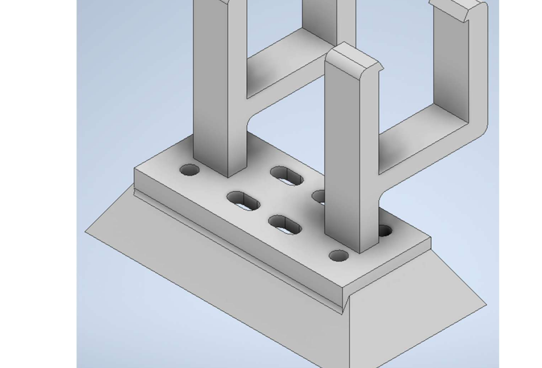
- Designed sensor-mount geometry to support practical placement of distance and colour sensors for bin detection, obstacle sensing, and navigation behaviour.
- Collaborated with teammates across mechanical, sensing, electronics, software, PCB, battery, grabbing-mechanism, packaging, and testing constraints so the robot could be treated as a full system.
Results and current status
The team finished second in the cohort with the final robot. The available project material shows a strong design/build contribution across the robot's mechanical and mechatronic subsystems. The project developed an autonomous robot architecture around a mecanum-drive base, fixed sensing layout, onboard storage, and gravity-assisted deposit mechanism. My documented work produced the drive selection and sizing, main CAD integration, motor/sensor/storage parts, storage-capacity analysis, and fabrication-ready drawings for key components.
Testing and iteration were used to improve practical details such as bracket rigidity, storage geometry, actuator clearance, and packaging. The CAD assembly shown on this page is a partial combined model of the main mechanical package. The PCB, battery package, and grabbing mechanism were owned by other team members and were not merged into that render.
Technical details
Requirements and competition constraints
The project brief forced the robot design to combine autonomy, sensing, route behaviour, mechanical storage, and practical manufacturability inside a compact physical envelope.
- Autonomy
- The robot was intended to complete its task autonomously after limited remote commands such as start, return, dispense, and emergency stop.
- Field behaviour
- The system had to navigate a tile/roadway environment, detect bins, avoid obstacles, classify bin colours, collect contents, deposit at assigned locations, and return bins close to their origin.
- Physical limits
- The final robot and non-computer hardware had to fit within the specified submission volume, while still carrying drive, storage, sensors, battery, and actuator hardware.
- Practical constraints
- Budget, battery energy, manufacturability, printability, access, reliability, and team assembly time all influenced the design choices.
Mechanical architecture and prototyping
The mechanical architecture had to make the autonomous behaviour physically possible: the drive needed precise alignment, the sensors needed stable mounting, and the storage/deposit system had to work reliably with real contents.
- Drive base
- A four-wheel mecanum base was selected to make sideways alignment possible without rotating the robot away from a forward-facing sensor frame.
- Motor mounts
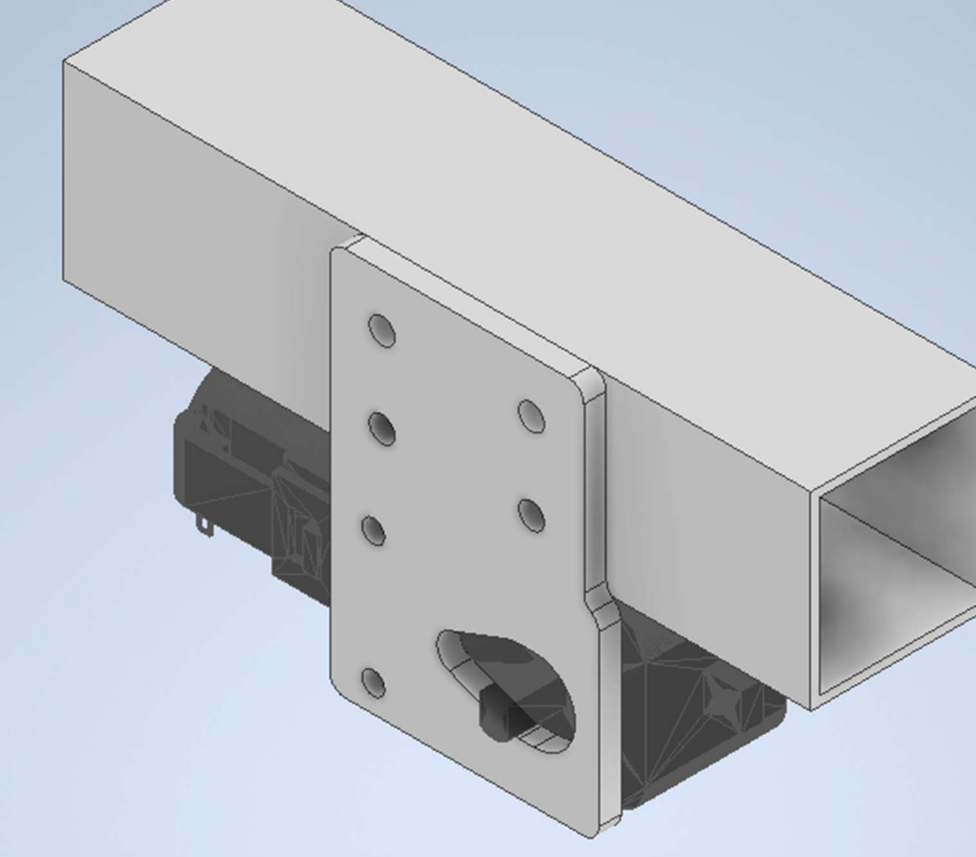
- Motor brackets were designed around the hollow chassis beam and checked for rigidity under expected loading.
- Storage
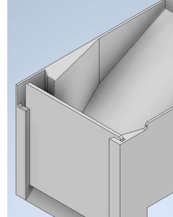
- The storage design used a tapered internal shape to reduce ledges and encourage contents to move toward the trapdoor during deposit.
- Deposit
- A front sliding trapdoor and linear-actuator concept supported controlled dumping without needing a large tipping mechanism.
- Battery interface
- Battery placement had to be considered with the team-owned battery subsystem so the mechanical package stayed balanced and accessible.
Sensor integration and navigation behaviour
The robot design linked sensor placement, chassis motion, and navigation behaviour. Sensor mounts were not just mechanical brackets. They controlled what the software could reliably see while the robot approached bins, followed the course, and avoided obstacles.
- Navigation behaviour
- The mecanum-drive concept supported lateral correction, in-place turning, and precise positioning near bins and deposit areas.
- Sensor integration
- IR/distance and colour sensor placement influenced the physical mount geometry, robot front-end layout, and expected approach behaviour.
- Speed constraints
- Drive speed was considered alongside sensor sampling and decision-making so the robot would not outrun its ability to detect bins or track the route.
- Deposit logic
- Storage capacity and trapdoor actuation informed the expected collect/deposit cycle, including the need to deposit contents before the storage was overfilled.
Virtual course model and task behaviour
The virtual course visual was built from the rules PDF as a lightweight portfolio diagram. It is not a physics simulation, but it shows the route logic the robot had to support: modular roadway following, bin approach, obstacle avoidance, delivery-point return, and colour-separated deposit.
- Road tiles
- The interactive model uses the original straight, curve, crossroad, delivery, chicane, and hairpin tile images extracted from the METR4810 rules PDF, plus a matching generated T-junction tile.
- Randomisation
- The browser procedurally generates a connected road graph with straights, curves, chicanes, hairpin-style turns, T-junction branches, crossroads, road ends, and valid roadside bin positions.
- Collection sequence
- The simulated robot first services all yellow-lid bins, returns to the yellow delivery zone, then repeats the loop for red-lid bins.
- Behaviour shown
- The model visualises route following, colour-based task sequencing, roadside bin pickup stops, delivery-point return, and onboard/deposited contents state.
- Scope
- This is a lightweight static portfolio model of task behaviour, not a physics simulation of wheel slip, sensor noise, actuator dynamics, or collision response.
Testing and iteration
The project was improved through practical iteration rather than a one-pass CAD model. Mechanical packaging, storage behaviour, and subsystem interfaces were checked against real build constraints.
- Motor bracket rigidity was checked against expected loading so the drivetrain would not deform excessively during operation.
- The storage mechanism was iterated to reduce internal ledges, improve actuator clearance, and support more reliable dumping.
- CAD packaging was revised around the real space taken by the drive, storage, sensing, and actuator subsystems, while allowing for team-owned battery, PCB, and grabbing-mechanism interfaces.
- Capacity estimates showed that storage volume and route strategy had to be treated together rather than assuming the robot could carry all contents at once.
- The team finished second in the cohort, with available local material showing subsystem design, CAD integration, drawing output, and partial validation notes.
Limitations and future material to add
- Add public photos or video of the completed robot and autonomous run once available and approved for portfolio use.
- Document final navigation software, state machine, sensor thresholds, and control behaviour with diagrams or screenshots.
- Add measured performance: successful bin pickups, deposit reliability, runtime, missed detections, obstacle responses, and detailed scoring breakdown if available.
- Refine the deposit mechanism for reduced jamming, easier cleaning/access, and higher repeatability under different waste contents.
- Improve the page with a complete final robot photograph or combined assembly render if one becomes available.