Project snapshot
- Problem
- Most high-performance servos are too tall or bulky for compact mechanisms with strict vertical constraints. The project investigated whether high torque and closed-loop position control could be achieved in an ultra-flat servo form factor.
- My role
- Mechanical, electrical, and control-system co-design, including requirements definition, component selection, gearbox trade study, control modelling, PCB design, CAD packaging, and verification planning.
- Tools
- MATLAB, Simulink, EasyEDA, CAD, STM32, DRV8213 motor driver, AS5600L magnetic encoder, coreless DC motor, PCB design, and geartrain modelling.
- Design targets
- Approximately 10-11 mm height envelope, 120 deg travel, 4.8-5 V power stage, 3.3 V logic, RC PWM interface, high stall torque, low backlash, and closed-loop position control.
- Outcome
- Completed concept design, CAD packaging, gearbox selection, control simulation, compact PCB design, sensor PCB design, and verification plan. Simulation met the torque target but not the original speed benchmark.
- Relevance
- Embedded systems, motor control, compact PCB design, mechatronic packaging, requirements traceability, simulation, control systems, and design trade-off analysis.
Visual proof
My contribution
- Defined the servo requirements and verification plan based on size, torque, speed, accuracy, backlash, power, and safety constraints.
- Selected and evaluated the motor, geartrain, encoder, motor driver, MCU, and power architecture.
- Designed a spur-then-worm drivetrain concept to provide high gear reduction, 90 deg output orientation, and low back-drivability.
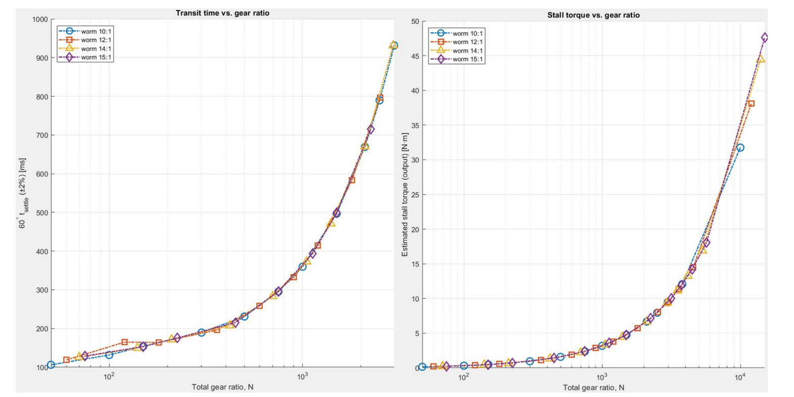
- Built MATLAB/Simulink models to evaluate gear ratios, step response, current limits, speed limits, overshoot, and torque output.
- Designed a compact main PCB and secondary sensor PCB for the motor-control electronics and position feedback system.
- Developed a verification plan covering PWM input, travel, step response, torque, backlash, thermal behaviour, current draw, and fault handling.
- Documented the trade-offs between height, torque, speed, efficiency, current draw, thermal limits, backlash, and manufacturability.
Results and current status
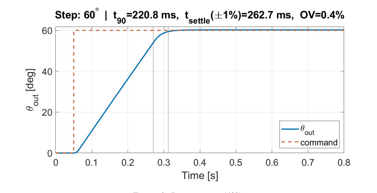
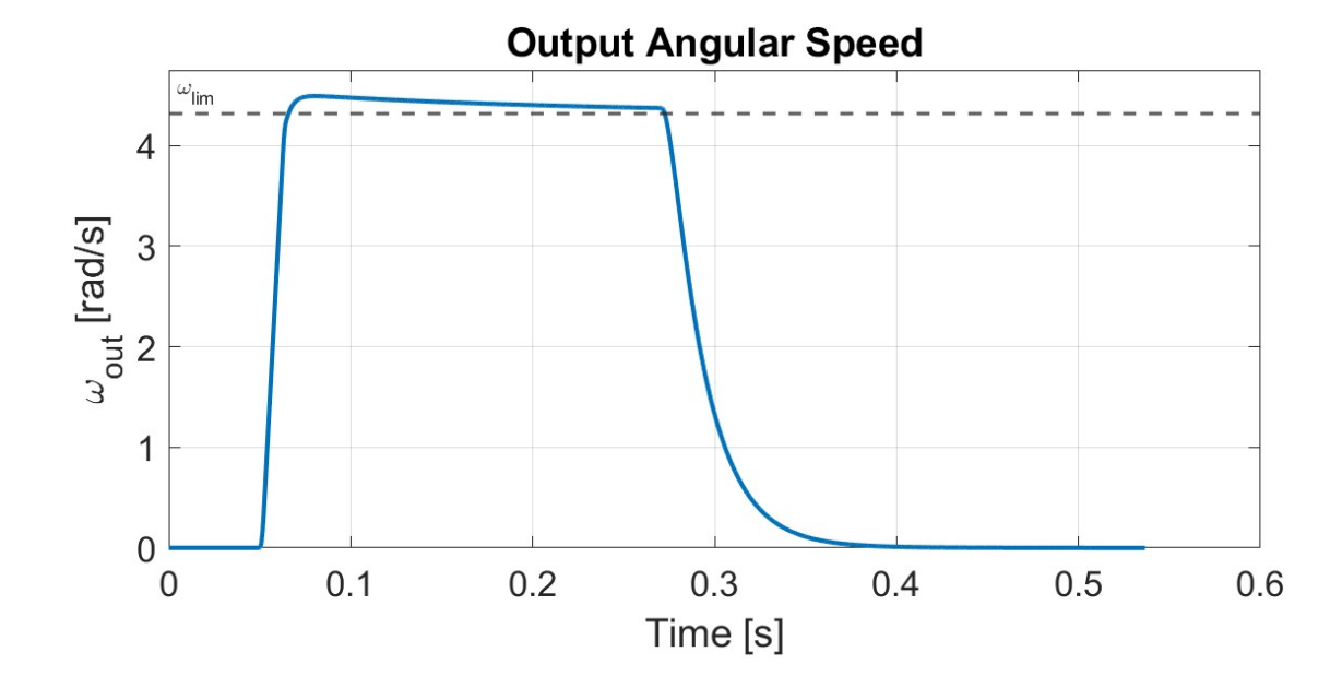
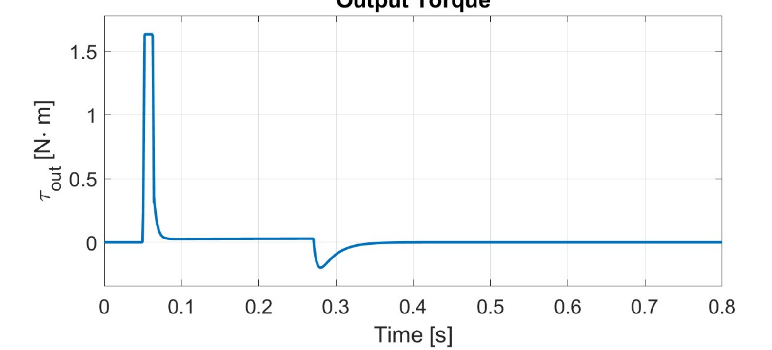
This project reached the design, modelling, and simulation-validation stage. The final concept used a compact brushed coreless motor, spur/worm geartrain, magnetic position sensing, a custom PCB architecture, and a triple cascaded position-velocity-current control model. The simulation achieved a 60 deg step response in approximately 0.263 s with about 0.4% overshoot and 0.156 deg steady-state error, while meeting the stall torque target at approximately 1.63 N*m.
The design did not fully meet the original 0.14 s per 60 deg speed benchmark, which made the main trade-off clear: the actuator could meet the torque target in simulation, but response speed would need improvement through gear ratio selection, drivetrain efficiency, voltage/current headroom, and thermal performance. Physical prototype testing and tuning were identified as the next stage.
Technical details
Requirements and constraints
The project was constrained by an unusually flat mechanical envelope while still aiming for meaningful servo performance. The requirements connected physical package size to electrical limits, mechanical output behaviour, controller response, and planned validation.
- Envelope
- Targeted an ultra-flat package around a 10-11 mm height constraint, with the motor, drivetrain, output stage, PCB, and casing packaged together.
- Motion
- At least 120 deg output travel with closed-loop position control and controlled response to RC PWM commands.
- Power
- 4.8-5 V power stage with 3.3 V logic, explicit current limiting, and planned brownout and fault handling.
- Torque
- Stall torque target based on high-performance servo requirements, with simulation estimating approximately 1.63 N*m.
- Speed
- Original benchmark of 0.14 s per 60 deg. Final simulation achieved approximately 0.263 s, identifying a clear design trade-off.
- Validation
- Verification plan covering timing, travel, step response, torque, backlash, current draw, thermal behaviour, endurance, and fault handling.
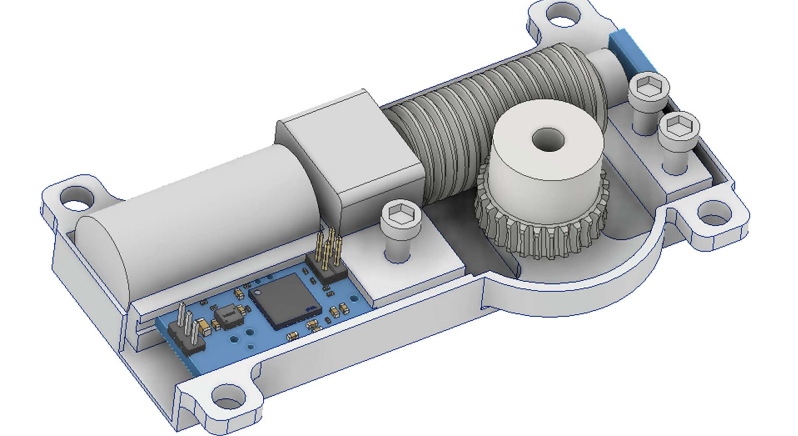
Mechanical architecture and drivetrain selection
The mechanical concept used a compact motor and high-reduction geartrain to fit torque multiplication, right-angle output motion, output support, and PCB packaging into a thin actuator body.
- Motor choice
- A compact brushed coreless DC motor was selected around speed, current, torque constant, diameter, mass, and packaging constraints.
- Drivetrain
- The selected concept used a spur-then-worm drivetrain to combine high reduction with a 90 deg output orientation.
- Gear ratio trade study
- Multiple spur and worm combinations were evaluated against transit time and stall torque, not only against static torque.
- Back-drivability
- The worm final drive reduced back-drivability, supporting holding behaviour without relying purely on continuous motor current.
- Packaging
- CAD packaging balanced the motor, output gear, worm, casing, bearing support, fasteners, PCB space, and connector access.
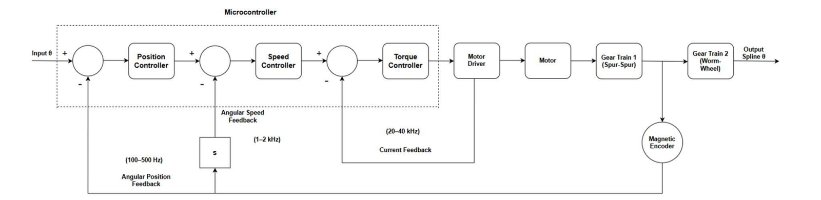
Control model and simulation
The MATLAB/Simulink model was used to evaluate whether the chosen drivetrain and electrical limits could deliver controlled position motion before physical validation. It was deliberately constrained by current, voltage, speed, and anti-windup behaviour.
- Architecture
- The simulation used a triple cascaded position-velocity-current control structure.
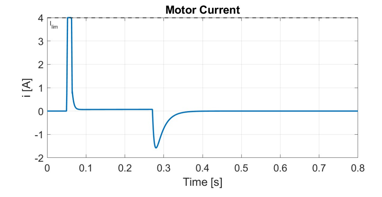
- Limits
- Current limiting, output-speed capping, voltage limits, and anti-windup behaviour were included so the model did not rely on unrealistic drive behaviour.
- Simulation result
- The simulated 60 deg step reached approximately 0.263 s with about 0.4% overshoot and 0.156 deg steady-state error.
- Trade-off
- The model met torque and accuracy targets in simulation, but the speed benchmark remained the main improvement path.
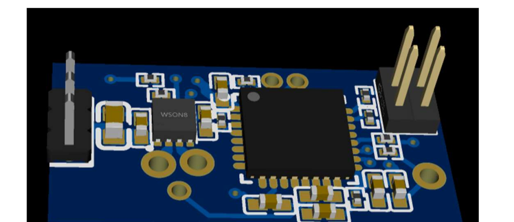
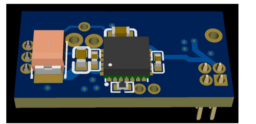
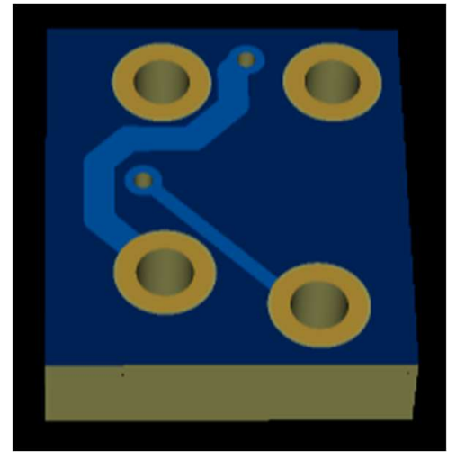
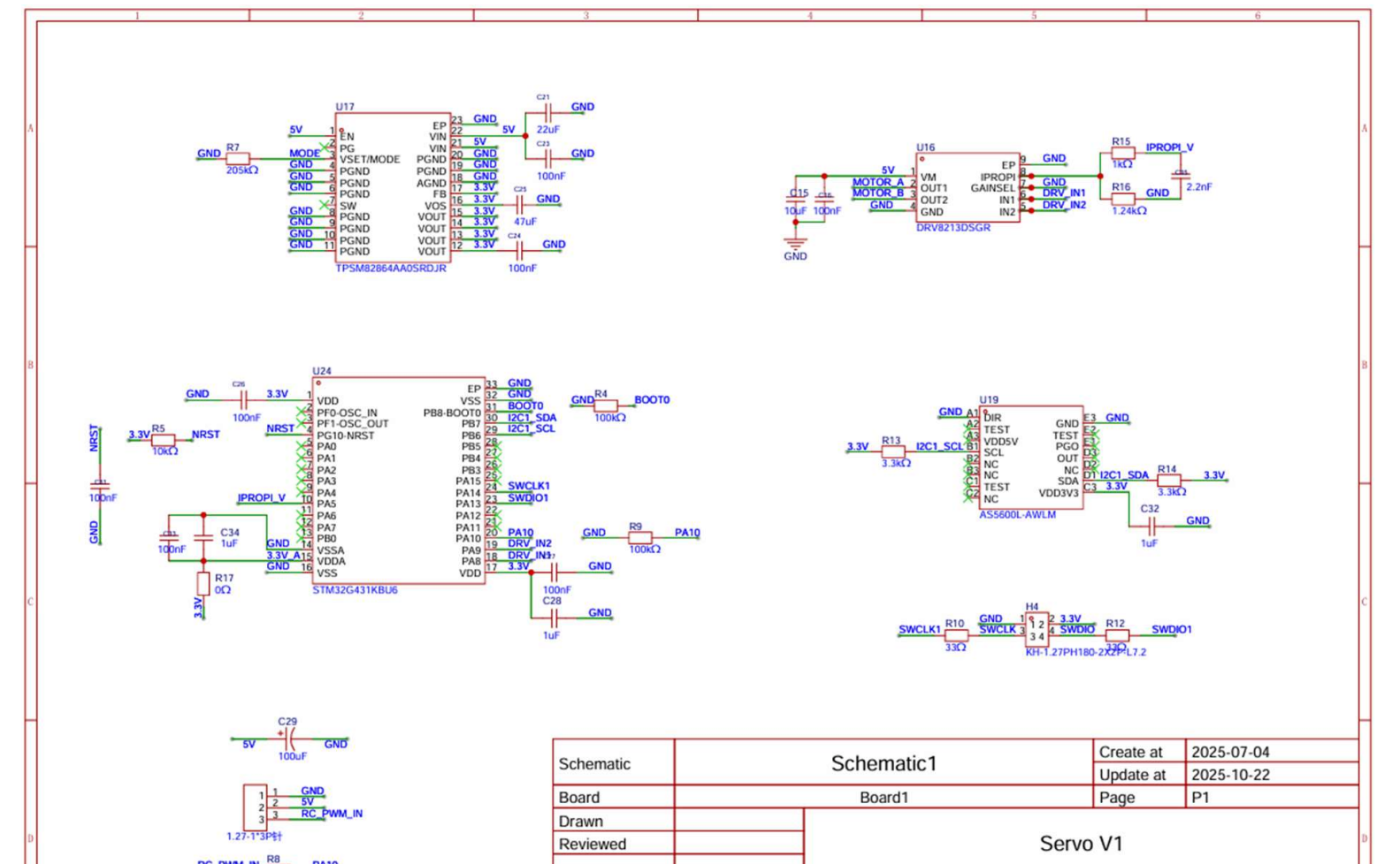
Electronics and PCB design
The electronics were split between a main motor-control PCB and a secondary sensor PCB. This separated power-drive packaging from output-position feedback while keeping the boards small enough for the actuator body.
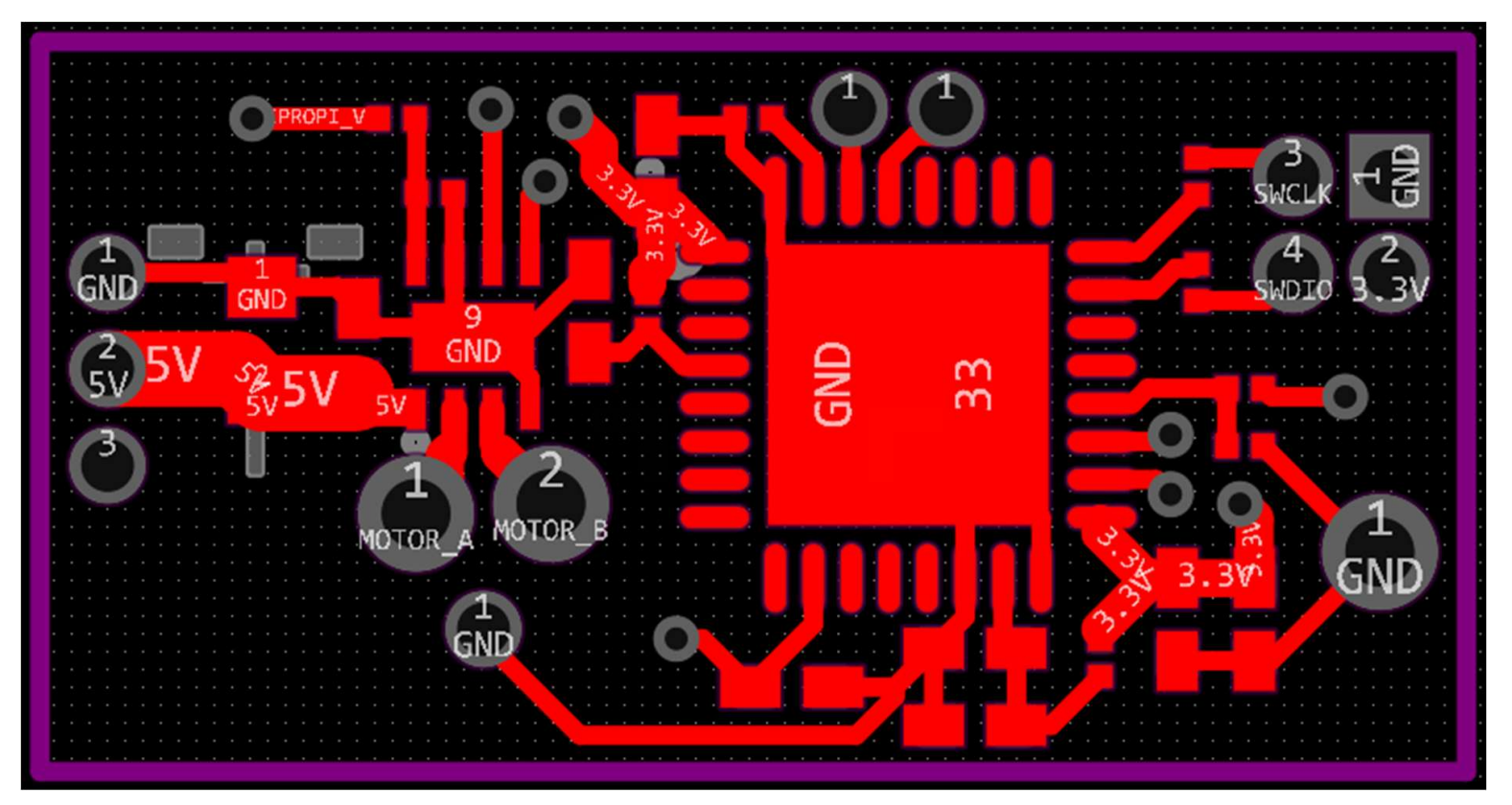
- Main PCB
- Compact motor-control PCB designed around the MCU, DRV8213 H-bridge motor driver, power path, connectors, decoupling, and programming access.
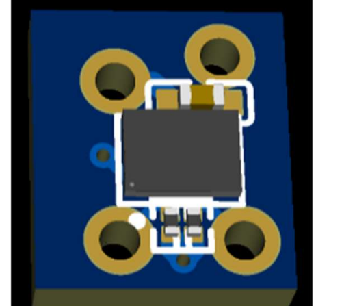
- Sensor PCB
- Secondary PCB designed around the AS5600L magnetic encoder for compact output-position feedback.
- Power architecture
- 5 V power stage and 3.3 V logic considered alongside current sensing, filtering, fault detection, and staged bring-up.
- Bring-up plan
- The electronics were designed with planned tests for power rails, programming, PWM input, encoder feedback, motor output, current limiting, and thermal behaviour.
Verification plan
The verification plan was used to connect design goals to specific future tests. This kept the project grounded in how the actuator would eventually be proven, not only how it was simulated.
- Check RC PWM timing, command range, jitter, and direction with test signals and oscilloscope measurements.
- Measure output travel, backlash, no-load 60 deg step response, overshoot, steady-state error, and repeatability.
- Use a lever-arm torque rig to validate stall and continuous torque against the simulation estimate.
- Measure current draw, voltage droop, temperature rise, and fault behaviour under load and stalled conditions.
- Compare measured plant behaviour against the MATLAB/Simulink model, then retune the cascaded controller using real data.
Results, limitations, and future work
- Physically assemble the actuator and complete staged PCB bring-up before claiming hardware validation.
- Validate step response, torque, current, voltage droop, backlash, thermal behaviour, and repeatability on the bench.
- Improve the speed result through gear ratio selection, drivetrain efficiency, voltage/current headroom, and thermal management.
- Refine mechanical tolerances, lubrication, output support, casing fit, and manufacturability after prototype testing.
- Tune firmware against measured actuator dynamics rather than only simulated plant parameters.