Project objective
The goal was to design and simulate a 6DOF robotic arm as a practical mechatronics system, not just a visual animation. The project was intended to build understanding of how industrial-style robot arms are modelled, controlled, tested, and validated before physical implementation.
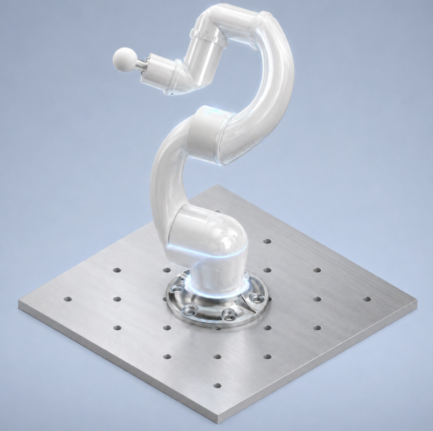
Visual proof
Design requirements
- Create a realistic 6DOF serial manipulator architecture with defined link dimensions and joint layout.
- Import or recreate the CAD structure for MATLAB/Simulink and Simscape Multibody simulation.
- Build a kinematic model suitable for inverse kinematics and Cartesian trajectory testing.
- Simulate controlled motion through planned Cartesian paths rather than only animating the CAD model.
- Analyse reachable workspace and identify unreachable regions, singularity issues, and practical limits.
- Prepare the model for eventual physical control using Robstride motors.
System overview
The robot uses a 6DOF serial manipulator layout with realistic link dimensions and a joint arrangement suitable for CAD modelling, kinematic analysis, and eventual motorised control. The simulation work focused on defining the link structure, solving inverse kinematics, generating smooth Cartesian motion, and checking whether target poses sit inside a usable region of the workspace.
- L1
- 0.119 m
- L2
- 0.230 m
- L3
- 0.200 m
- L4
- 0.0772 m
- L5
- 0.1252 m
- L6
- 0.155 m
My technical contribution
I worked across the mechanical layout, CAD-to-simulation workflow, robot kinematic model, link length definition, inverse kinematics setup, trajectory planning, workspace analysis, and motion simulation. I also investigated how the system could eventually be controlled using Robstride motors, including how joint-space and Cartesian-space movement would be handled.
Modelling and simulation workflow
- Mechanical layout and CAD modelling
- CAD-to-simulation translation
- rigidBodyTree and Simscape Multibody modelling
- Inverse kinematics setup
- Smooth 5 second Cartesian trajectory generation
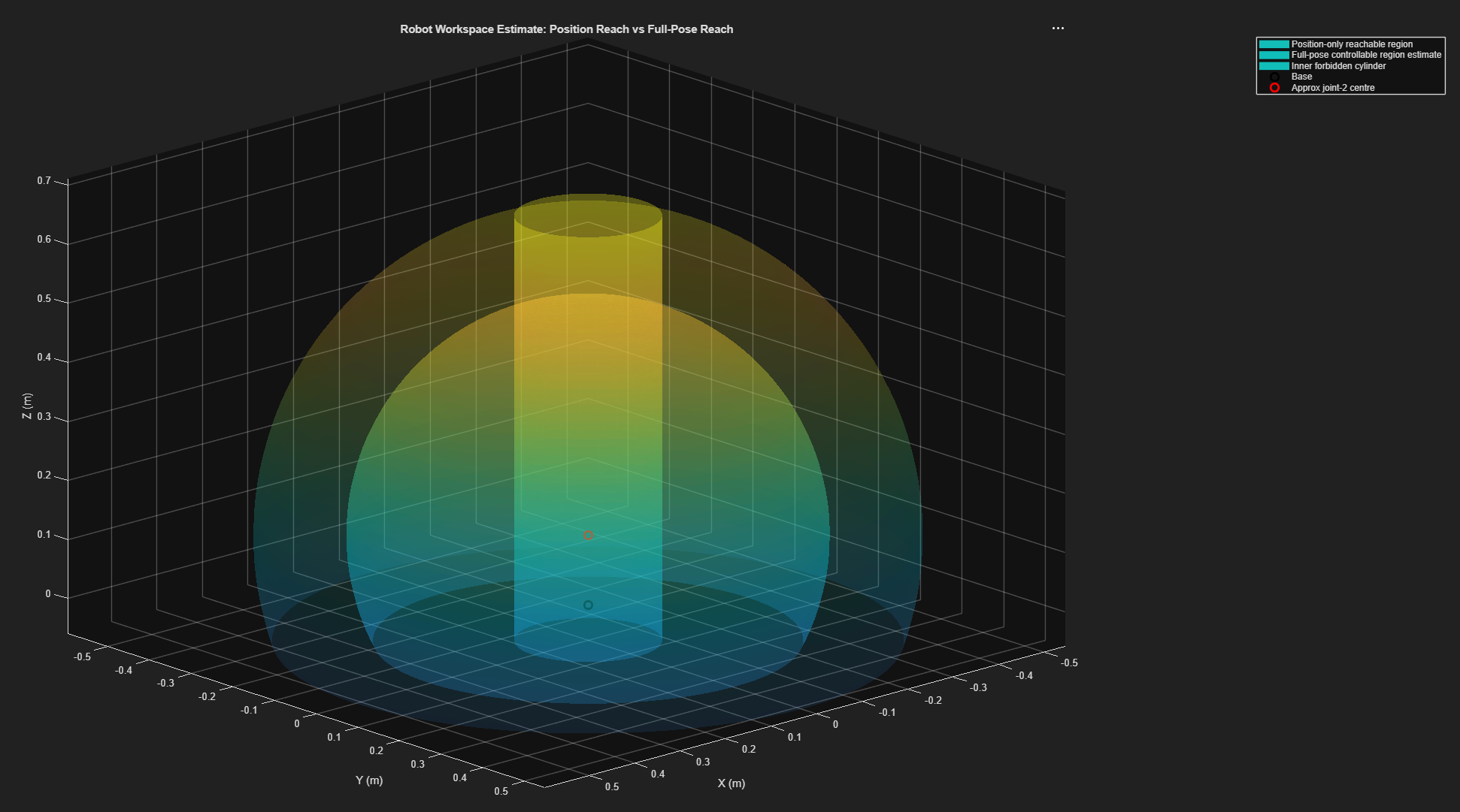
- Workspace and reachability evaluation
A smooth Cartesian trajectory was tested over a 5 second motion using smoothstep-style motion planning. The simulated path-following result showed very small error for the tested trajectory, which indicated that the planned path and inverse kinematics model were working correctly within that region of the workspace.
I also recorded a pose-sweep simulation where the end-effector holds a constant XYZ position while roll, pitch, and yaw change. This helps separate orientation control from translational motion and gives a clearer check of the model's full-pose behaviour.
Results and evaluation
The project successfully produced a simulated 6DOF robot arm model with defined link lengths, inverse kinematics, trajectory planning, and workspace analysis. The arm could follow planned Cartesian paths accurately within the tested workspace region. The work also highlighted practical limitations that matter before physical control, including unreachable targets, singularity behaviour, and the need to validate the usable workspace rather than assuming every pose is achievable.
Future improvements
- Improve the physical implementation and refine the mechanical packaging around real actuators.
- Integrate and test Robstride motor control rather than only planning around motor selection.
- Refine the control interface for joint-space and Cartesian-space commands.
- Test joint limits, singularity avoidance, reachable workspace limits, and real-world motion accuracy.
- Add final simulation plots, CAD drawings, and motor architecture diagrams when ready for public release.