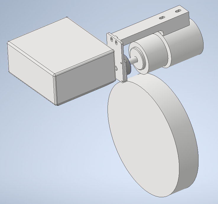
The electrical / microcontroller section was developed because the test rig needed one control pathway rather than separate disconnected systems. The Nucleo sits between the computer and the machine hardware: the PC provides the operator interface, while the Nucleo handles the machine-facing signals for the VFD, encoder, and Keyence laser measurement path.
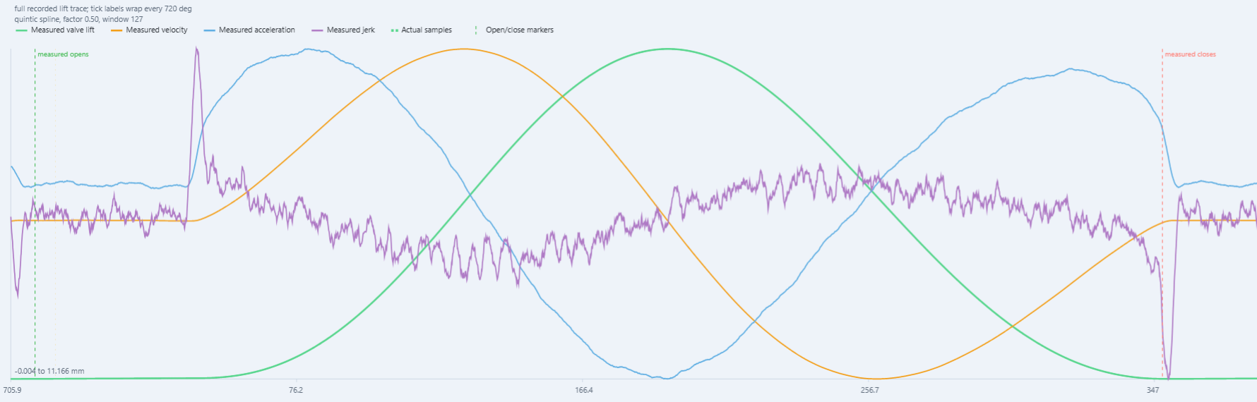
The core technical challenge is synchronisation. RPM and cam angle need to come from the encoder, valve lift comes from the Keyence laser, and the run state comes from the programmed VFD/RPM sequence. Those streams have to line up so the saved data can be analysed as cam lift versus camshaft angle rather than as unrelated live readings.
Hardware integration plan
- Already available
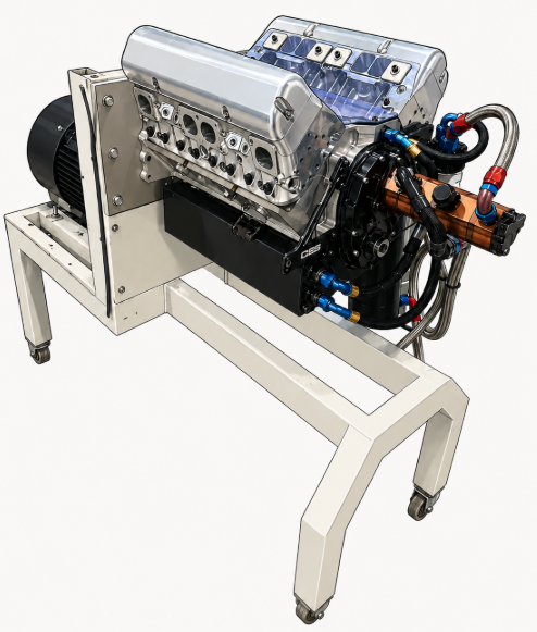
- PC, Keyence LK-G82 laser head, LK-GD500 controller, Keyence laser cable, and VFD.
- Controller to add
- NUCLEO-H753ZI board used as the machine-interface controller between the PC, VFD, encoder, and laser measurement path.
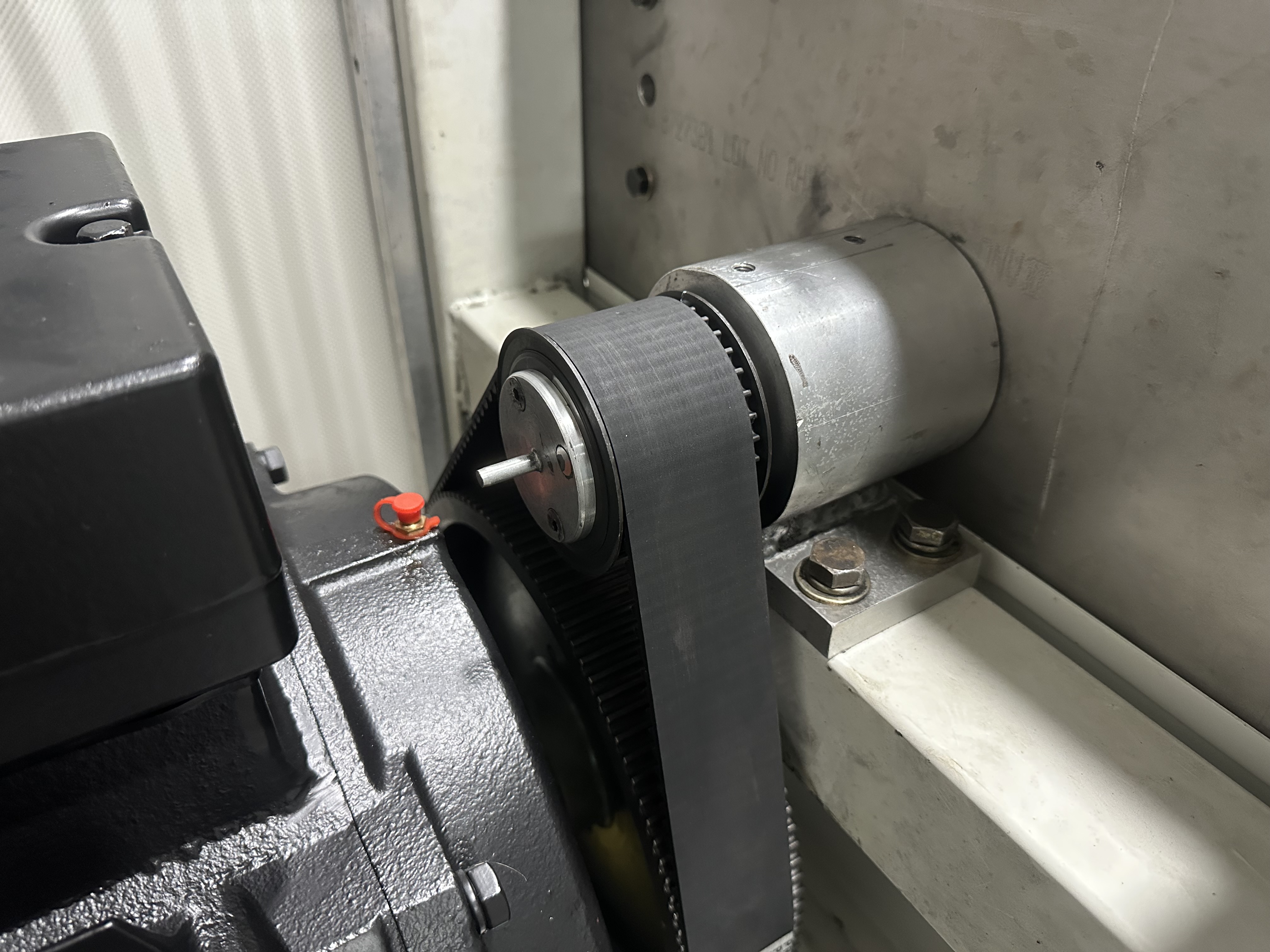
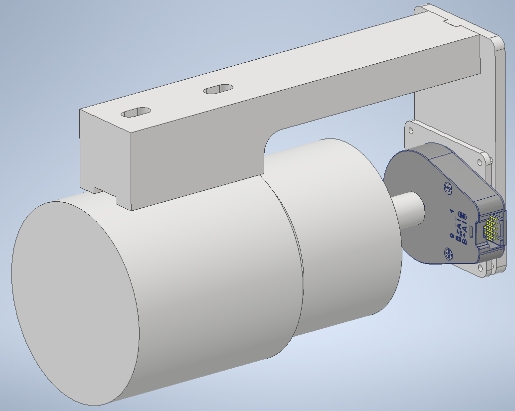
- Encoder chain
- US Digital H6-1024-IE-D encoder into a 26C32 / RS422-style incremental encoder receiver board, then into Nucleo timer / index inputs.
- Laser chain
- LK-GD500 OUT1(V) and OUT1 0V through shielded analog cable into a high-speed 0-10 V to 0-3.3 V laser ADC front-end, then into the Nucleo ADC.
- VFD chain
- Nucleo UART/GPIO into a TTL/UART-to-RS485 interface board, then RS485 A/B wiring to the VFD control terminals for Modbus-style control.
- Power and wiring
- Dedicated 5 V DIN-rail supply for encoder/interface power, shielded analog cabling, short low-voltage wiring, RS485 twisted pair, and termination where required.
Assembly sequence
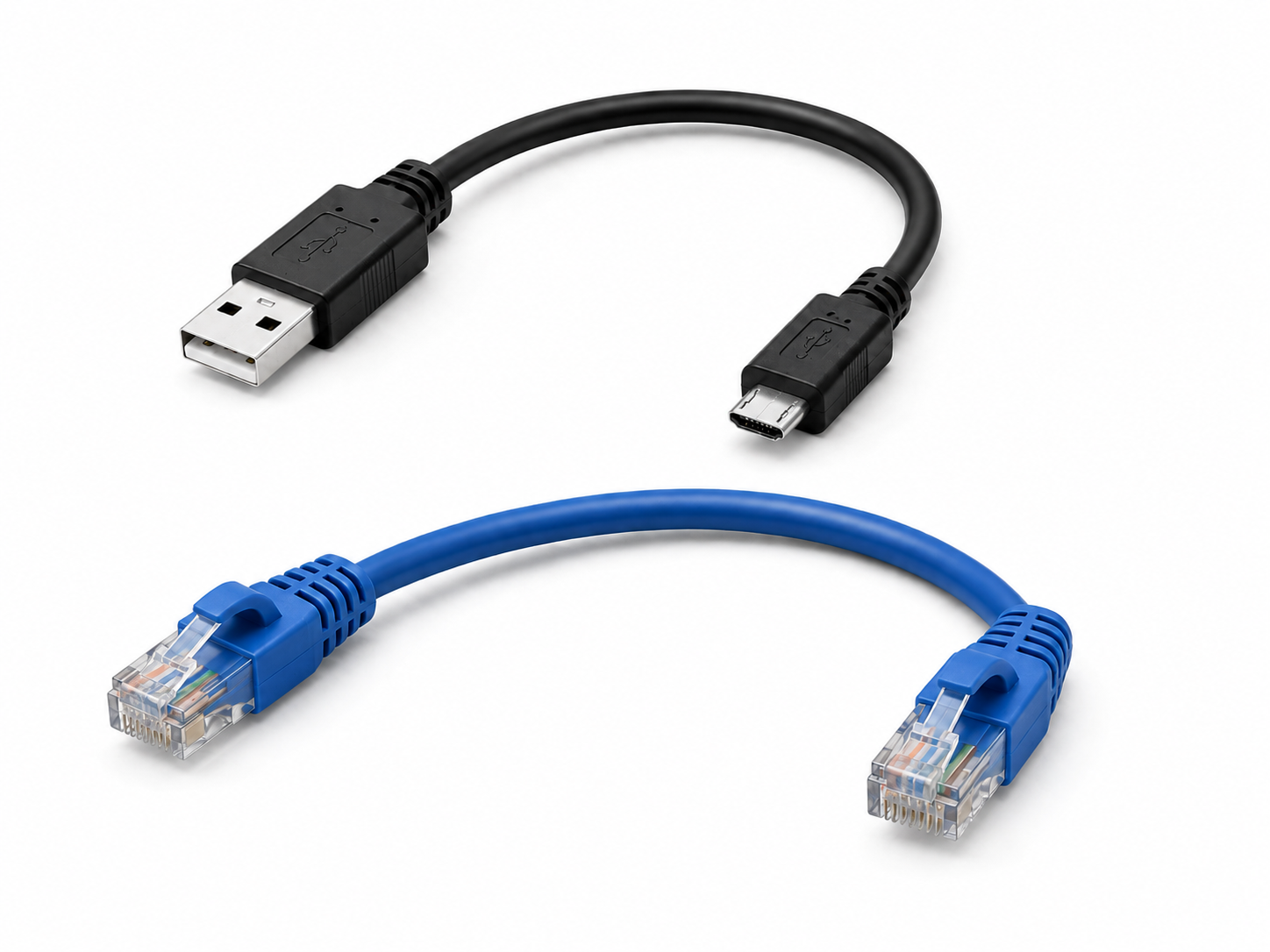
- Connect the PC to the Nucleo over USB for programming/debugging and over Ethernet for programmed runs, telemetry, and recorded data transfer.
- Wire the encoder through the shielded encoder cable and RS422 receiver board so the Nucleo reads true shaft RPM, angle, and index reference.
- Route the Keyence LK-GD500 analog output through a fast protected ADC front-end instead of wiring the 0-10 V output directly to the microcontroller.
- Wire the RS485 interface board between the Nucleo and VFD so the computer program can command speed through the microcontroller path.
- Keep emergency stop, guarding, VFD enable/safety, and motor isolation as hardwired safety functions rather than relying on software control.
I/O and signal summary
- VFD command
- RS485 / Modbus-style command path planned from the Nucleo through an interface board to the VFD control terminals.
Control output
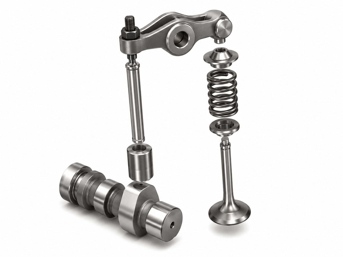
- Encoder A/B/Z
- Differential encoder signal through an RS422 receiver board into timer and index inputs for RPM and cam angle.
High-speed digital feedback
- Keyence laser
- LK-GD500 0-10 V analog output scaled and protected before entering a Nucleo ADC channel.
Analog measurement
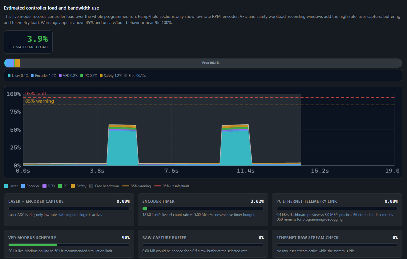
- Dashboard telemetry
- Controller status, measured RPM, run state, sample rate, capture state, and capacity estimates returned to the local HMI.
Status and data
- High-speed samples
- Time, target RPM, measured RPM, cam angle, lift, and derived values saved separately from the low-rate live display.
Logged data
- Safety signals
- E-stop, guarding, motor isolation, and VFD enable treated as hardwired machine safety functions.
Safety boundary
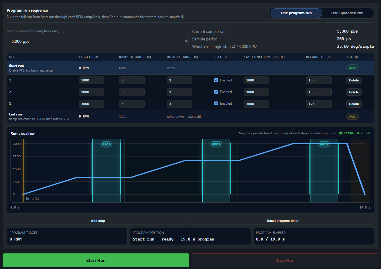
Run state model
- Idle Machine at standstill, dashboard ready, run profile not active.
- Armed Run profile loaded, recording windows checked, controller ready for command sequence.
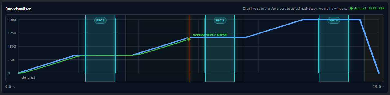
- Ramping VFD target changes while measured encoder RPM is monitored against the desired profile.
- Hold Target speed held long enough for stable measurement or recording trigger conditions.
- Record High-speed encoder and laser capture active inside the selected recording window.
- Ramp down Commanded speed returns to zero and the VFD is brought back to standstill.
- Review Saved data is opened for lift, velocity, acceleration, jerk, and cam-angle analysis.
- Fault Abnormal state intended to stop the run and require operator review before continuing.
Measurement and sampling model
- Encoder resolution
- US Digital H6-1024-IE-D incremental encoder, 1024 CPR, 4096 counts per revolution in x4 decoding, about 0.088 degrees per count.
- Speed-rating check
- The H6 encoder is rated to 10,000 rpm mechanically, so the final mounting shaft speed must be checked before commissioning.
- Laser path
- Keyence LK-GD500 OUT1(V) configured as 0-10 V, scaled through a fast protected front-end for the Nucleo ADC rather than a slow PLC-style converter.
- Saved sample rows
- Each saved row is intended to contain time, target RPM, measured RPM, cam angle, laser lift, derived values, VFD telemetry, sample rate, and encoder count.
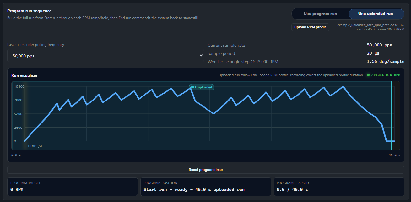
- Capture rates
- Dashboard model supports saved capture rates from 1,000 pps through 50,000 pps for maximum-detail laser and encoder captures.
- Live preview
- The browser display is decimated to roughly 50-100 points per second, while saved run data remains separate from the live preview.