Placement objective
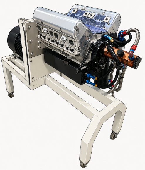
The placement connected software, measurement, and machine behaviour in a real camshaft manufacturing environment. The public case study is centred on developing the measurement and control concept for a Spintron-style camshaft test rig.
Engineering context
The Spintron concept sits in a practical test-system space: understanding camshaft behaviour through controlled high-speed rotation, true RPM and angle feedback, laser lift measurement, and logged analysis data.
- Spintron / camshaft dyno concept development.
- High-speed RPM and encoder measurement planning.
- Laser displacement sensing and valve-lift measurement concepts.
- VFD control and microcontroller-based data acquisition architecture.
- Engineering software for remote run setup, live visualisation, logging, and post-run analysis.
My technical contribution
My contribution was in the engineering tools and system concepts rather than general workshop labour. I worked on the Spintron/camshaft dyno architecture for synchronised encoder, laser displacement, VFD, STM32, and PC-dashboard data flow.
Results and evaluation
The Spintron concept developed a clear measurement architecture for controlled RPM, encoder angle, laser displacement sensing, and logged data analysis. The work is presented as a system-design and software-prototype case study, with hardware commissioning and measured validation still treated as future work.
Project case study
Rather than duplicating the same technical material here, the project page below contains the detailed objectives, design requirements, visuals, technical contribution, results, and next validation steps.